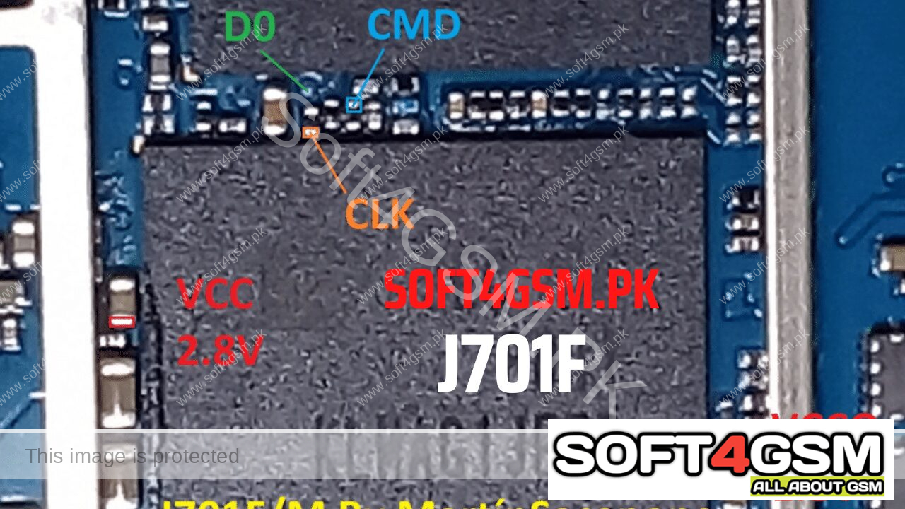
Samsung Galaxy J7 Nxt ( SM-J701F ) ISP Pinouts BY SOFT4GSM.PK
Here You’ll easily get the Samsung __ ISP Pinout connection by following the full guide below. By using the ISP Pinout, you can bypass FRP lock or reset user data on your device via EasyJTAG Plus Box, Medusa Pro 2 , UFI BOX or any other tool you have. Check out the below guide.
Remove Pattern Lock, Screen Lock, Finger Lock with Easyjtag, Medusa box , UFI Box or any other box you can easily solve with this method. if you are new technician in android software, here I’ll tell you, if the error occurs of USB not recognized then your USB is not working. if a battery is not charged, your USB socket will not work properly and can’t repair your phone. So make sure that you have charged battery and usb jack is working properly.
By using the Samsung “MODEL NAME” “STORAGE TYPE” ISP Pin OUT, you can easily restore the stock ROM, bypass FRP lock, Remove MDM, Lost Mode (Device Lock, No Downloads Mode, No Recovery), Dead boot repair, repair Partition Direct by Easy Jtag Plus Or UFI Box. Here we will show you the tested and working image of the ISP pinouts for the “MODEL”.
What is ISP Pinout?
ISP means “In-System Programming”.
In-System Programming (ISP) allows communication to take place with a target chip without the need to remove it. The main advantage of this method is to communicate with a target chip eMMC, eMCP or UFS without removing it from the board. It brings higher speed for data exchange compared with but it requires great soldering skills.
Hardware Process:
You need to take the rear case away from your phone. The unplug the battery, display and other things from motherboard, and take the motherboard out and put it in a safe place.
On your motherboard, locate the six “STORAGE TYPE” points. The points are Dat 0, CLK, CMD, GND, VCC, and VCCQ. You will require to cut the steel cover to reveal them.
Bring the any box you have and take the adapter out from it. You will see the exact same pins in the adapter I have mentioned in the previous step.
Solder the 4 pins: Dat0, CLK, CMD, and GND with jumpers between the motherboard and the adapter. Left the VCC and VCCQ for the USB to power them out.
Put the adapter inside the UFI box. Connect the box to the computer.
Connect the motherboard to the phone’s battery. Then, put the USB cable on the phone and connect it to the computer.
